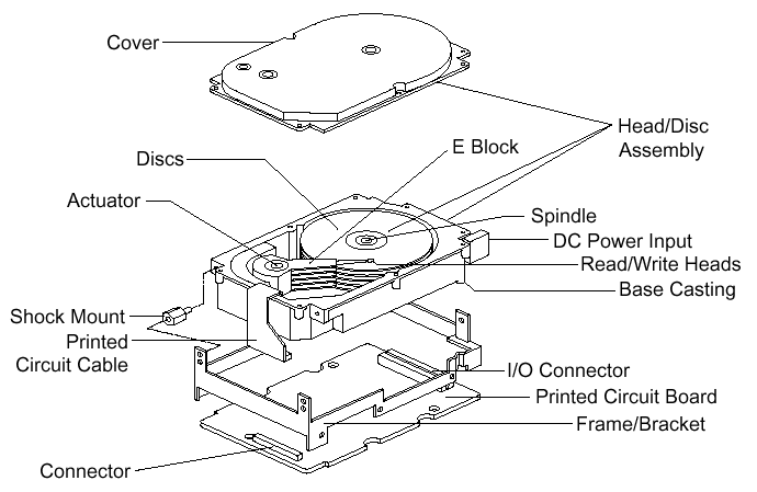
As an illustration, I’ll describe here in words how the various components in the disk interoperate when they receive a request for data. Hopefully this will provide some context for the descriptions of the components that follow in later sections.
A hard disk uses round, flat disks called platters, coated on both sides with a special media material designed to store information in the form of magnetic patterns. The platters are mounted by cutting a hole in the center and stacking them onto a spindle. The platters rotate at high speed, driven by a special spindle motor connected to the spindle. Special electromagnetic read/write devices called heads are mounted onto sliders and used to either record information onto the disk or read information from it. The sliders are mounted onto arms, all of which are mechanically connected into a single assembly and positioned over the surface of the disk by a device called an actuator. A logic board controls the activity of the other components and communicates with the rest of the PC.
Each surface of each platter on the disk can hold tens of billions of individual bits of data. These are organized into larger “chunks” for convenience, and to allow for easier and faster access to information. Each platter has two heads, one on the top of the platter and one on the bottom, so a hard disk with three platters (normally) has six surfaces and six total heads. Each platter has its information recorded in concentric circles called tracks. Each track is further broken down into smaller pieces called sectors, each of which holds 512 bytes of information.
The entire hard disk must be manufactured to a high degree of precision due to the extreme miniaturization of the components, and the importance of the hard disk’s role in the PC. The main part of the disk is isolated from outside air to ensure that no contaminants get onto the platters, which could cause damage to the read/write heads.
 |
| Exploded line drawing of a modern hard disk, showing the major components. Though the specifics vary greatly between different designs, the basic components you see above are typical of almost all PC hard disks. |
| Original image © Seagate Technology Image used with permission. |
Here’s an example case showing in brief what happens in the disk each time a piece of information needs to be read from it. This is a highly simplified example because it ignores factors such as disk caching, error correction, and many of the other special techniques that systems use today to increase performance and reliability. For example, sectors are not read individually on most PCs; they are grouped together into continuous chunks called clusters. A typical job, such as loading a file into a spreadsheet program, can involve thousands or even millions of individual disk accesses, and loading a 20 MB file 512 bytes at a time would be rather inefficient:
- The first step in accessing the disk is to figure out where on the disk to look for the needed information. Between them, the application, operating system, system BIOS and possibly any special driver software for the disk, do the job of determining what part of the disk to read.
- The location on the disk undergoes one or more translation steps until a final request can be made to the drive with an address expressed in terms of its geometry. The geometry of the drive is normally expressed in terms of the cylinder, head and sector that the system wants the drive to read. (A cylinder is equivalent to a track for addressing purposes). A request is sent to the drive over the disk drive interface giving it this address and asking for the sector to be read.
- The hard disk’s control program first checks to see if the information requested is already in the hard disk’s own internal buffer (or cache). It if is then the controller supplies the information immediately, without needing to look on the surface of the disk itself.
- In most cases the disk drive is already spinning. If it isn’t (because power management has instructed the disk to “spin down” to save energy) then the drive’s controller board will activate the spindle motor to “spin up” the drive to operating speed.
- The controller board interprets the address it received for the read, and performs any necessary additional translation steps that take into account the particular characteristics of the drive. The hard disk’s logic program then looks at the final number of the cylinder requested. The cylinder number tells the disk which track to look at on the surface of the disk. The board instructs the actuator to move the read/write heads to the appropriate track.
- When the heads are in the correct position, the controller activates the head specified in the correct read location. The head begins reading the track looking for the sector that was asked for. It waits for the disk to rotate the correct sector number under itself, and then reads the contents of the sector.
- The controller board coordinates the flow of information from the hard disk into a temporary storage area (buffer). It then sends the information over the hard disk interface, usually to the system memory, satisfying the system’s request for data.
| The PC Guide Site Version: 2.2.0 – Version Date: April 17, 2001 © Copyright 1997-2004 Charles M. Kozierok. All Rights Reserved. |
This is an archive of Charles M. Kozierok’s PCGuide (pcguide.com) which disappeared from the internet in 2018. We wanted to preserve Charles M. Kozierok’s knowledge about computers and are permanently hosting a selection of important pages from PCGuide.
